I. Foundation of Selection: Definition of Electrical Characteristics of IT Loads
1.1 Essential Attributes of Loads
The core circuit of power modules in IT equipment (servers, switches, storage devices, etc.) follows the structure of “rectifier → inductor → capacitor”. Among these components, the inductor (L) is critical in determining load properties, as it suppresses current pulses after rectification.
According to the inductive reactance formula XL = 2πfL (with a power frequency f of 50Hz), inductors cause the AC side to exhibit inductive impedance, leading to current lagging behind voltage (with a phase difference of 0°~90°). In compliance with GB 17625.1, the total harmonic distortion (THD) of the input current for IT loads is ≤5%, and the proportion of inductive reactive power ranges from 20% to 30% (with a power factor of 0.7~0.9 lagging).
1.2 Common Misconceptions
The “capacitive indication” at the UPS output is a result of compensation, not an inherent property of the load:UPS systems are configured with capacitive impedance to offset the inductive reactive power of IT loads. When the capacitive compensation exceeds the inductive reactive power slightly, the meter displays a leading power factor of 0.8~1.0. However, once the compensation module is disconnected, the load-side power factor immediately reverts to 0.7~0.9 lagging. It is important to avoid misidentifying the compensation result as an inherent attribute of the load.
II. Technical Parameters and Applicable Scenarios of Three Types of Load Banks
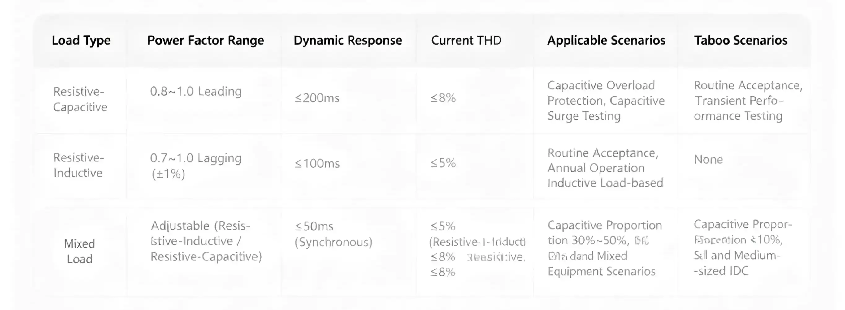
2.1 Resistive-Capacitive Load Banks (Power Factor: 0.8~1.0 Leading)
Technical Parameter Requirements
Power adjustment range: 10%~100% of rated power, with a step size ≤5%.
Dynamic response speed: ≤200ms (step load switching time).
Current THD: ≤8% (under rated load).
Applicable Scenarios
Verification of capacitive overload protection: Simulate scenarios such as excessive capacitive compensation or abnormal DC UPS operations to test the diesel generator’s excitation overvoltage protection (winding temperature ≤110℃, in compliance with GB 1094.1).
Capacitive impact testing: Apply a 30% capacitive load suddenly within 100ms to verify the response speed of the automatic voltage regulator (AVR), requiring a voltage recovery time ≤3s.
Inappropriate Scenarios
Routine acceptance testing: Unable to simulate the inductive reactive power of IT loads, resulting in ineffective testing of the diesel generator’s excitation system adjustment capability.
Transient performance testing: Insufficient response speed fails to capture transient deviations in voltage/frequency during load steps.
2.2 Resistive-Inductive Load Banks (Power Factor: 0.7~1.0 Lagging, Adjustable)
Technical Parameter Requirements
Power factor adjustment: 0.7~1.0 lagging, with an accuracy of ±1% (core indicator).
Dynamic response speed: ≤100ms (matching the step characteristics of IT loads).
Current THD: ≤5% (consistent with the harmonic characteristics of IT loads).
Reactive power adjustment: 0 to rated reactive power.
Applicable Scenarios
Routine acceptance testing:
Steady state: Operate at 100% load for 2 hours, with voltage deviation ≤±5% and frequency deviation ≤±1% (GB/T 2820.5).
Transient state: Apply 50%/100% load suddenly, requiring a maximum voltage drop ≤20% (recovery time ≤5s) and a maximum frequency drop ≤12% (recovery time ≤10s).
Overload: Operate at 110% load for 1 hour, with exhaust temperature ≤600℃ and oil temperature ≤95℃.
Annual operation and maintenance testing:
Verify performance degradation of the diesel generator’s excitation windings and fuel system after long-term operation.
Data centers with inductive load proportion >70%:
Fully matches the load characteristics of servers and refrigeration equipment (compressors, fans).
2.3 Hybrid Load Banks (Adjustable Resistive-Capacitive + Resistive-Inductive)
Technical Parameter Requirements Branch parameters: The resistive-inductive branch meets the requirements in 2.2, and the resistive-capacitive branch meets the requirements in 2.1.
Coordinated control: Synchronization of load switching across multiple branches ≤50ms.
Applicable Scenarios
Scenarios with capacitive load proportion of 30%~50%: For example, data centers equipped with DC UPS and energy storage devices.
Hybrid equipment scenarios: Data rooms with both AC IT equipment (inductive) and DC equipment (capacitive). The proportion is set based on the measured load profile (e.g., 70% resistive-inductive + 30% resistive-capacitive).
Inappropriate Scenarios
Capacitive load proportion <10%: The deviation between test data and that of pure resistive-inductive load banks is ≤3%, so no additional investment is needed.
Small and medium-sized IDCs: Increases equipment complexity and costs, with lower cost-effectiveness than pure resistive-inductive load banks.
Table 1: Comparison of Technical Parameters and Scenarios for Three Types of Load Banks

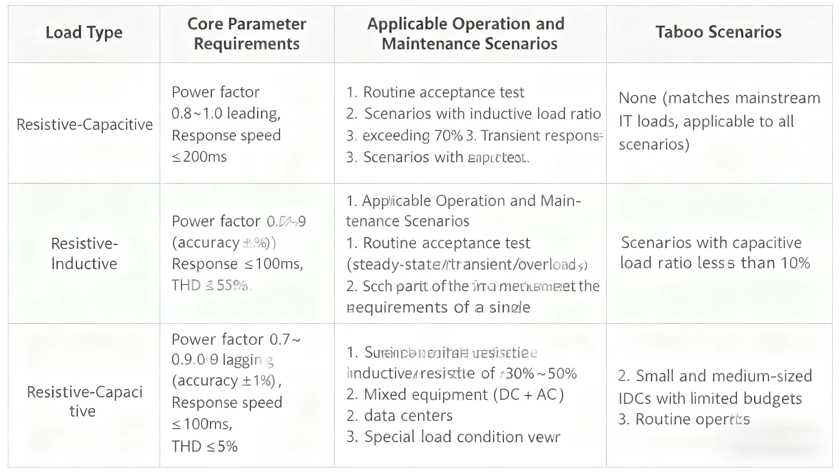
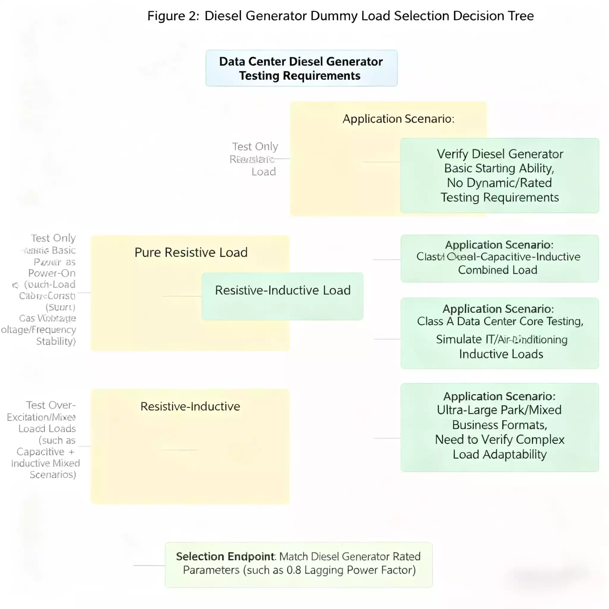
Table 2: Load Bank Type Adaptation Table for Diesel Generator Testing

III. Technical Process for Load Bank Selection
3.1 Load Profile Measurement (Core Preparatory Step)
Testing Instruments
Power analyzer (e.g., Fluke 438-II), clamp ammeter, temperature recorder.
Measured Parameters
Power factor:
Calculate the 24-hour fluctuation range by cabinet type (server cabinet, storage cabinet, refrigeration cabinet), and use the minimum value as the selection benchmark.
Reactive power:
Calculate the peak value using the formula [Image placeholder] to ensure the load bank covers the required reactive power.
Load step:
Record the maximum sudden increase/decrease amplitude within 24 hours (e.g., 40% load step) to match the load bank’s response speed.
Data Output
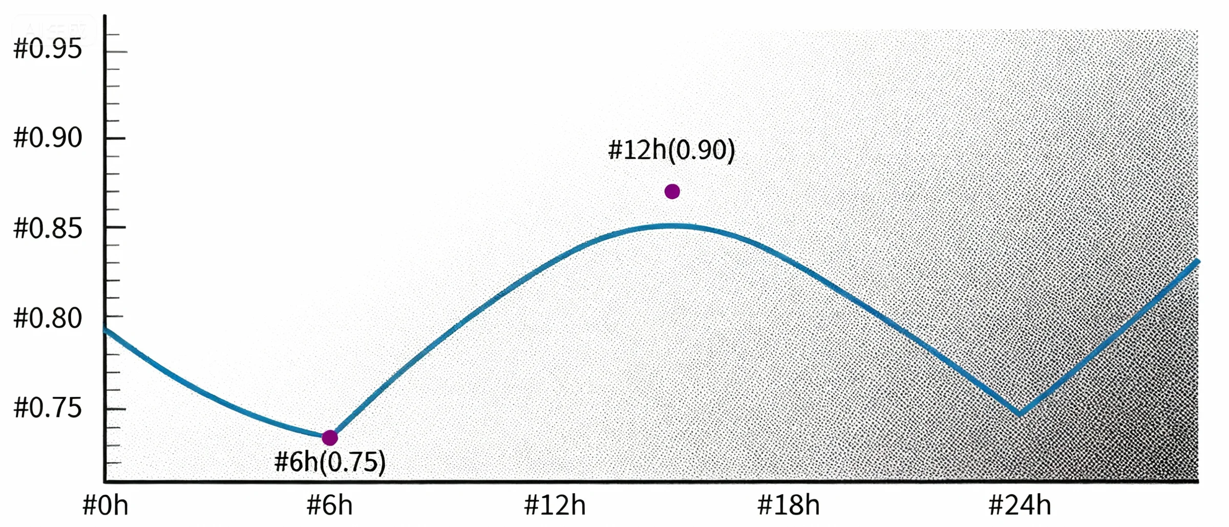
Generate a 24-hour power factor variation curve (see Example in Figure 1) and a load power distribution

3.2 Equipment Accuracy Verification
Metrological Calibration Report
Check the calibration report from a provincial metrology institute (e.g., National Institute of Metrology, China) within the past year, focusing on verifying:
1. Power factor: Error ≤±1% in the 0.7~0.9 lagging range.
2. Current THD: Error ≤±0.5% under rated load.
Dynamic Response Testing
Use an oscilloscope to measure the step load switching time, ensuring it meets ≤100ms (for resistive-inductive load banks) and ≤200ms (for resistive-capacitive load banks).
Temperature Rise Testing
Operate at 100% load for 2 hours, with inductor winding temperature ≤105℃ (GB 1094.1).
3.3 Testing Scheme Development
Steady-State Testing
Operate at 100% load (set according to the measured power factor) for 2 hours, and record the following parameters every 10 minutes:
1. Electrical parameters: Output voltage, frequency, excitation current.
2. Mechanical parameters: Oil temperature, coolant temperature, exhaust temperature.
Transient Testing
Sudden load application: Switch from 50% to 100% load, and record transient deviations in voltage/frequency and recovery time.
Sudden load removal: Switch from 100% to 50% load, and verify that the frequency overshoot is ≤5%.
Overload Testing
Operate at 110% load for 1 hour, and monitor the action thresholds of protection devices (e.g., overvoltage, overtemperature).
3.4 Data Review and Deviation Analysis
Deviation Indicators
1. Voltage recovery time: Deviation between test value and actual load-carrying value ≤1s.
2. Fuel consumption: Deviation between test value and theoretical calculation value ≤5% (theoretical fuel consumption = power × fuel consumption rate).
Causes of Deviation
1. Insufficient response speed: If the load bank’s dynamic response exceeds 100ms, transient data will be optimistically biased.
2. Excessive THD: If the load bank’s THD exceeds 5%, harmonic losses of the diesel generator increase, leading to higher measured fuel consumption.

IV. Technical Requirements for Special Scenarios
4.1 Aging Diesel Generators (Operation >8 Years)
1. Power factor setting: Reduce the lagging power factor by 0.05~0.1 (e.g., from 0.8 to 0.75) to simulate the attenuation of reactive power-carrying capacity due to aging excitation windings.
2. Testing focus: Ensure the excitation current increase is ≤15% under 110% overload (≤10% for new diesel generators) to prevent winding overheating.
4.2 Parallel Operation of Multiple Diesel Generators (≥2 Units)
1. Uniform load type: Use the same type of load bank (e.g., all resistive-inductive) to avoid uneven load distribution (load difference ≤10%, GB 50174).
2. Synchronous control: Ensure the synchronization of step switching across multiple load banks is ≤50ms to prevent excessive circulating current in parallel diesel generators.
4.3 Cost Optimization (Small and Medium-Sized IDCs)
1. Parameter trade-offs: A power factor accuracy of ±2% and a response speed of 150ms can reduce costs by 30%, meeting the needs of non-Class A data centers.
2. Priority to leasing: Choose leased equipment with metrological calibration reports to avoid fixed asset investment (reducing single-test costs by 50%).


